
Hi! As promised, here’s my progress so far. This post will also be the loose format of how I want to post these in the future. I intend to have four sections: what I’ve been up to, what new developments have come up, and what I have planned next, and if there’s any immediate opportunities to help. I also want these to be written casually so I don’t have to agonize over them, and so that they’re fully readable by technically experienced folks but also skimmable with occasional tl;drs for curious but not electronics literate onlookers.
What I’ve been up to
In ultra brief summary, my last week on this project was giving up on the LM334, which is a lovely chip if you want a precision low-amperage source (seriously I was getting stable single microamp precision), but it just has too many quirks for use as an on the fly adjustable current source. I’ve since committed to a dual opamp design I found on some blog somewhere and I haven’t looked back, because it seems to work perfectly. I designed a circuit, simulated it, it worked swimmingly, I laid it out on a PCB, ordered it, and ordered parts to build it out.
Here’s the blog post - I went with the “Two Op-Amp Topology”. It’s actually sick as hell. Here’s my implementation of it in SPICE:
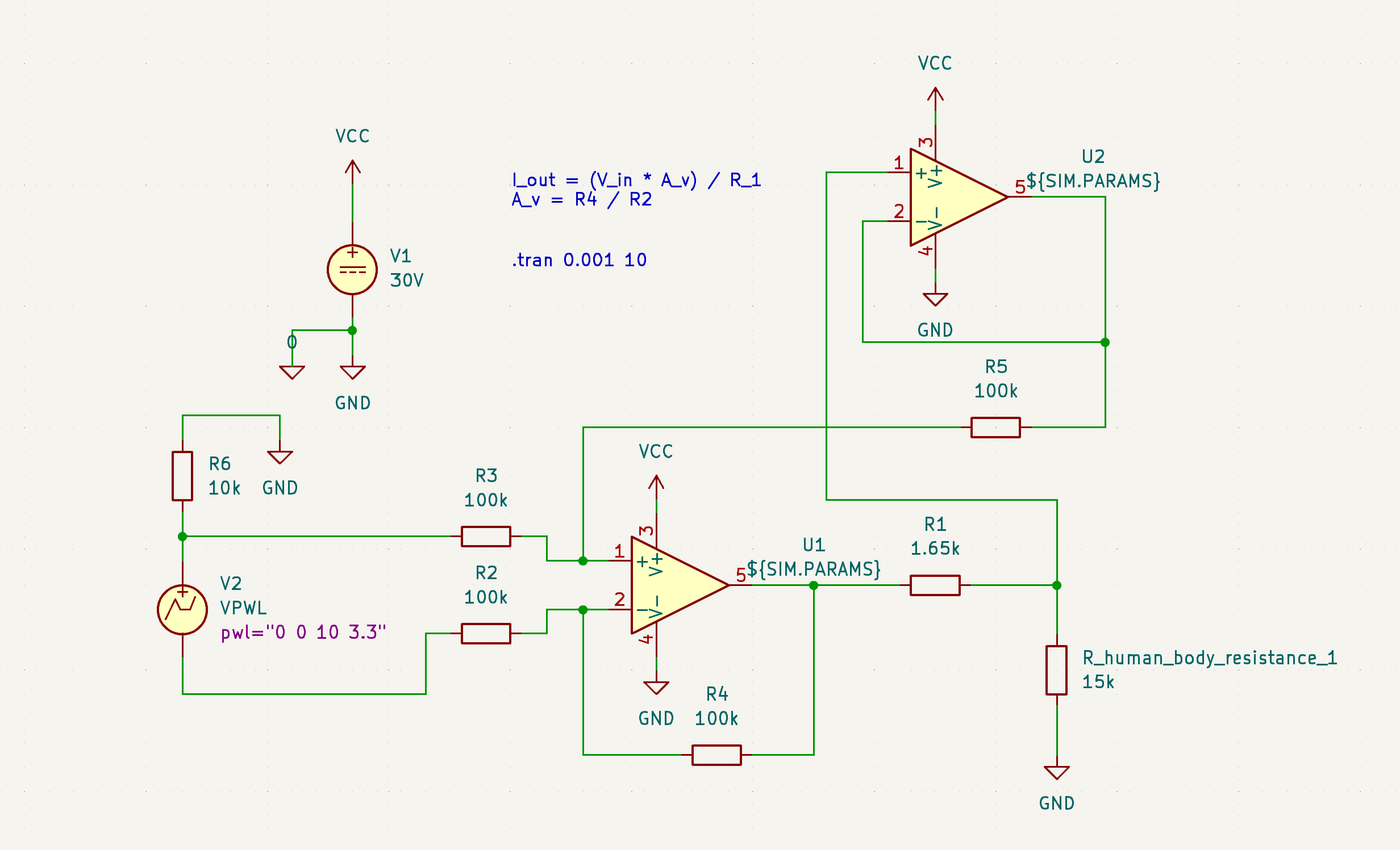
Something I’m really adamant about on in regards to safety (a core objective) is that this needs to have hard limits on both current and voltage. I’ve been able to design this in in the simulation, see:
It’s hard to tell exactly what’s going on here if you don’t know how to read circuit diagrams and also know how I set this up, but essentially, I’m varying the simulated human body resistance and looking for it to behave the same way as I do so. Even if the device can drive the amps into you by current and voltage availability alone, it’s hard capped at 2 mA, with the voltage limit imposed by whatever voltage you give the opamp and the current limit imposed by (basically) the resistance of R1. (More technically, this is a voltage controlled current source, and the voltage applied to V_current_set is divided by the resistance of R1 for the value of the current sourced from U1A.) All bodies are not the same resistivity, all parts of the same body are not the same resistivity, and even the same part of the same body is not always going to be the same resistivity. It’s important that the administered current and voltage don’t vary based on user, body part, and et cetera. This is an important safety and performance feature that most other DIYers I’ve seen have omitted. This is exactly what I was hoping to see this design do and it nailed it.
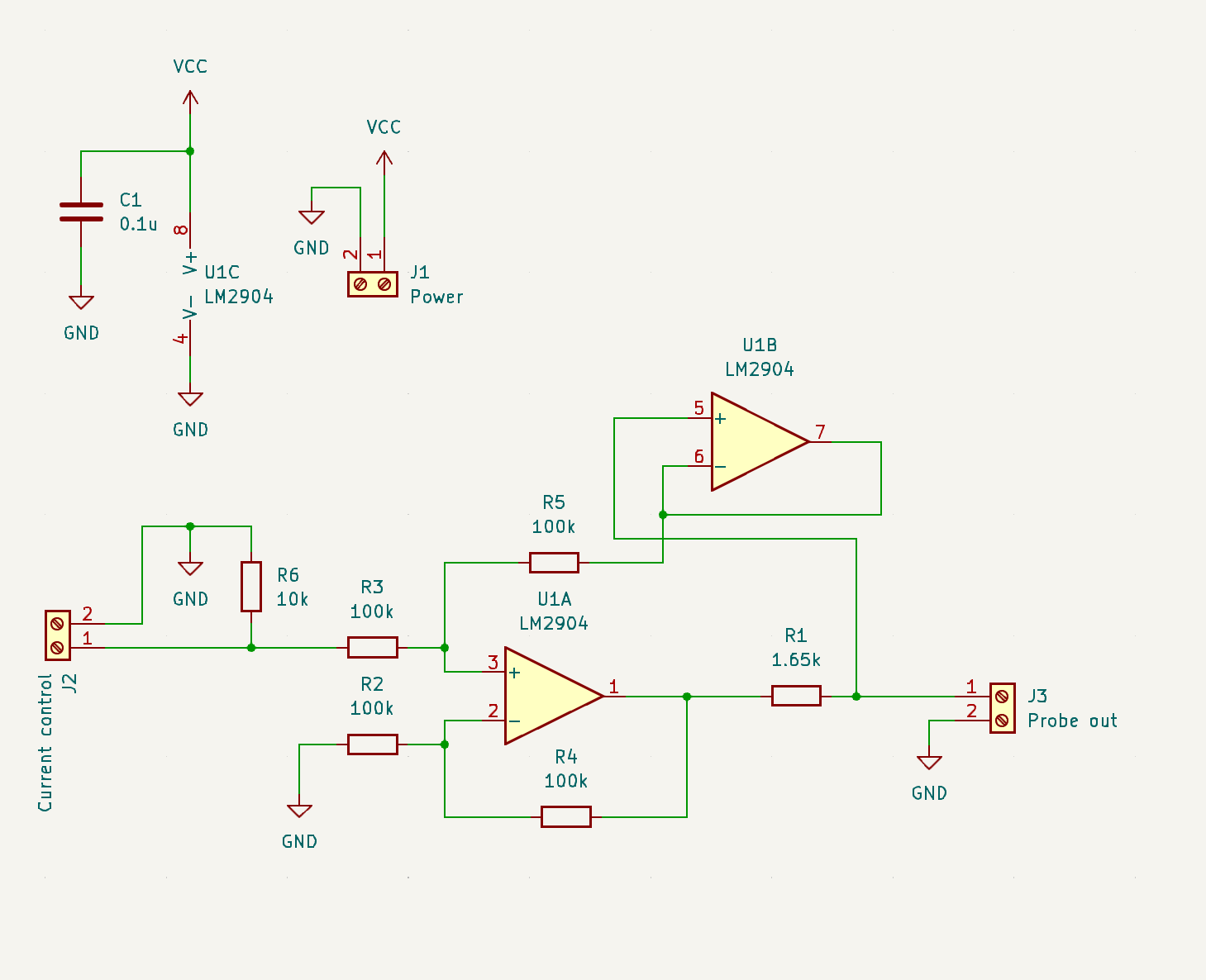
So, I drew up the circuit, routed the PCB, and with that, we’re here:
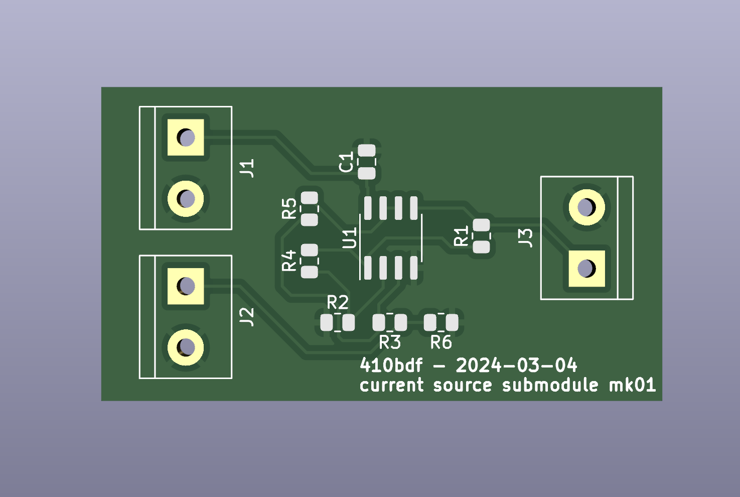
It comes in the mail next week! Thanks to @lapis and @macerated_baby_presidents for the JLCPCB rec, I didn’t get a populated board, I wanna build it myself, but their service has been nice so far and I look forward to ordering a populated board from them soon to test accessibility! I left off test points, status LEDs, and some other stuff. That’s okay. I’ll do better next time. :comfy: The important thing is that this circuit is the circuit I’m rolling into 1.0.
Non-technical tl;dr: This is the circuit that takes in a normal power source and conditions it into the correct amount of power, specifically voltage and current, to kill hair follicles in a safe and controllable fashion.
New developments
I decided to give up on microcontrollers. 💔 For now.
Adding a microcontroller adds a lot of pros, and a lot of cons. The upshots are that it really makes this into something cool, something with flipper zero vibes - I’d be able to add a splash screen with graphics and I’d be able to explicitly list voltage/current/pulse time numbers on a display, I’d be able to shift a number of changes into firmware over hardware, meaning quicker debugging, and more. The downside though, is that I’d likely be requiring end users to flash a firmware build (not accessible, breaking one of the core 3 objectives), I’d be dealing with a data bus like SPI to get the screen to run, which is a pain to debug, and I’d be opening myself up to feature creep. I decided to axe it for now and just do everything by knobs with no screen to be able to get y’all a working basic finished project sooner. ❤️🩹
Next up
My availability is somewhat limited for the next week, but I want to at least build out this board and test it on the bench to make sure it actually applies the current I designed it to. While I’m waiting for this, I can start to design the other parts of this circuit. I have the power conditioning designed, next up I need to design the following, roughly in this order:
- instead of just loose inputs I put voltages on, I want to make knobs that set the amperage.
- I need to add timing circuitry so that instead of just an on/off, the user pushes a button and the device outputs current for an amount of time configured by a second knob.
- I need to add power conditioning, so that a 9V battery, an 18650, or something like it can be boosted up to generate the voltage required to drive the current required to smoke ur hairs.
- Fit and finish. Oh, and all of the activation switch and applicator probe everything.
I can probably design 1 and 2 in the next week. I definitely won’t be able to actually build and test them until late next week, but now that I’m getting better at SPICE, I can simulate them, which will give me the (probably ill-founded) confidence to order boards without testing anything on the bench first. Likely no updates until mid next week due to this.
Any ways to help?
First of all, ask to be put on the tag list if you want updates! Knowing there are other real life human beings who think this is cool helps me a lot. Besides that, no electronics help at the moment, I don’t have enough done to have any shared work to propose. Soon, I’ll start thinking about the current probe, and I’ll need help thinking about that. Besides that though, just get hype and if you know anyone who knows anything about electrolysis hair removal, let them know about this so they can be here for discussions if they want to be!
I’ll see y’all some time next week for the next update. Thursday of next week or earlier. It’s in my calendar. Bye!
tag list: @ComradeEd@lemmygrad.ml, @raven@hexbear.net, @Wake@hexbear.net, @BountifulEggnog@hexbear.net, let me know below if you want to be added or removed!
Your username inspired me:

ugh I was so hoping someone would do this, you’re amazing, thank you


We つける a little 火
Speaking of, did you know that apparently it’s pretty common in West Asia to つける a little 火 to epilate?
Just an interesting tidbit in service of nothing in particular.
I found a YouTube link in your comment. Here are links to the same video on alternative frontends that protect your privacy:
I find the amount of inaccessibility to needed procedures grim, but I still wish to express how deeply impressed I am with transfeminine women’s and enbie’s resourcefulness and will. I remember seeing someone perform orchiectomy on themselves and now this. I am in awe.
Death to whatever conditions cause that to be someone’s best option, Jesus.
I think I recall that diy orchi post, iirc their last comment was getting an infection

Oh shit I didn’t know. I hope she’s okay.
I remember seeing someone perform orchiectomy on themselves [sic]
I’m losing my own patience chestno govoria
I’m so sorry. 🫂
All things considered it isn’t even that I dislike the little guys necessarily, I just don’t want testosterone in my bloodstream, and grabbing the nearest nozhik seems like a more reliable way to sort that out than having to deal with my bica getting seized by customs again
If you like the shape you could get implants. I think orchiectomy should be vastly more available than it is. I’m so sorry for you. :((((
 those experiments on mice will one day soon lead to a testis-to-ovary gene editing injection
one suggestion for future builds:
Schottky diode between VCC + GND near the connector in case the battery gets connected backwards
Oh right. Tagging people in a post doesn’t ping them. You need to do that in a comment.
@ComradeEd@lemmygrad.ml @raven@hexbear.net @Wake@hexbear.net @BountifulEggnog@hexbear.net new DIY electrolysis post.
Would you mind adding me to the ping list?
thanks lol I appreciate you, I’ll put the tag list in a comment next time
Tag me, I love this stuff!
add me to the ping! this is cool!
I’ve got enough knowledge to populate and likely troubleshoot a board like this but not enough to tell you anything you don’t already know! I’d totally build one and test it out or help manufacture it or whatever if that becomes necessary
oh also jlcpcb is probably a faster and more capable vendor esp if you might eventually want other services but I’ve also used OSHPark with decent results. honestly tho the big players may have the economies of scale to beat them on speed and price. and probably exotic board types too i just like the purple solder mask tbh lol
OSHpark is so expensive and doesn’t do assembly but I will say that they offer a very easy “click button get PCB” distribution solution via the sharing center. I’ve used that before, on some board that the author lost the source files for.
yeah it can’t beat any of the overseas ones on price. But for the little projects I’ve used it for it’s been cheap enough that I didn’t care it wasn’t technically “a good deal”. For bigger PCBs that may be different. It was pretty fast (maybe I got lucky?) but not really better than jlc on that either even in the best case
idk why I have any loyalty to it… I mean I don’t really but I’ve only ordered pcbs a handful of times and I think the first one was one of those links you mention. someone on hackaday made a Pi Zero GPIO to VGA adapter board that I wanted to try (worked astonishingly well tbh even with “best I could find at the surplus store” through hole resistors)
I do like the purple and gold tho, and I’ve heard their quality is better in some ways that I almost certainly don’t need
DIY electrolysis doohickey
I came in hoping you were making another
 but your project is also super cool and rad.
Best of luck!
Wanna add me to the tag list?
feedback for V2:
- round the board corners and include mounting holes. Render looks like KiCAD, from experience it’s not too annoying and JLCPCB won’t charge extra.
- good job keeping it single layer. I guess you could try to get a ground pour under the opamp but idk if it matters. Thicker traces, esp for power inputs, never hurt as long as you have room.
- This looks easy to assemble but I think that for V2 you are gonna have to choose between
- Assembled by board house, in which case keep things surface-mount and shrink board as small as you can for price
- Assembled by end user, in which case keep the board spacious and probably move to through-hole parts. You and I know that surface mount is not hard, but it intimidates a lot of noobs and many of them are working without flux or a temperature controlled iron.
- For non-power connectors, I’m a fan of putting a symbol in the schematic and just making the symbol’s footprint a connector. I had to do a bunch of head scratching to figure out that J2 is a variable voltage source. (J1 is clear, J3 I get that there’s no such thing as a probe schematic symbol.)
- It’s probably cheaper to do separate resistors like you have, but be aware that you can get resistor arrays e.g. if you want to cut down on BOM or board space.
- Do you actually need 30V for reasonable skin resistance values? The lower you can get this the better. Commodity boost converters may be cheaper than whatever parts you’re ordering in small quantities. I would again suggest a USB battery bank and not a “raw” battery. Battery management for lipos is annoying, 9Vs are not very power-dense, and standalone battery housings are surprisingly expensive (meaning a dollar or two, but every bit counts for BOM) for what they are.
- yep yep test points. they’re free, go wild. For manually-assembled stuff I expect to do a lot of debugging on, I often include two holes that I connect with a wire so I have something to clip a scope probe onto.
- you might want to include a low-value resistor in series w probe with test points on either side. Then you can measure resistance and hook up a scope to monitor the actually-applied current.
- watch out that JLC has a library of “preferred” parts, e.g. their 2904. If you haven’t already, pick parts from the library to reduce pain later
Yeah chip flashing is the bane of DIY electronics. The standard hobby solution for pulse generation is a 555, but that’s not actually very accurate over timescales of more than a few seconds. If it were me I’d want to throw in an ATTiny or something digital. It’s probably not JLCPCB price tier, but I know there are fabs that will also flash MCUs before assembly.
This is all amazing advice, I appreciate you for all of this, lemme do my best to address everything piece by piece:
- 100% gonna round board corners next time, I’ll probably add mounting holes too although this isn’t a board I plan to ever enclosure, this is basically an opamp breakout for debugging
- thanks I tried, although the bottom is poured so I still payed for a second layer. KiCAD defaulted to like 7 or 8 mil traces or something and since the current is capped at 2 mA on the output I called that good enough for now
- Throughout development I’m gonna assemble everything myself to keep costs low, and then the end goal is for the final product to be orderable 100% assembled by the board house with no additional solder touches required. We’ll see if I can do that
- another smort tip thank you
- I like 0805 because I can run traces under them and save on vias
 probably good advice for moving to a final version though!
 - 30V is just what I used in SPICE, I think I’ll take a page from /u/abbxrdy on Reddit (linked in my first post) and keep my voltage range from 6 V to 22 V, which is a boosted single 18650, which is convenient. I think power management is going to be the hardest part though, I have some reckonings coming up that I’d love your input on in next week’s post
- yep yep test points
 for now I was just gonna poke IC/resistor legs but that’s not sustainable for the rest of development, I like these too
 - really good idea on the shunt! I’ll do that
- I’m trying my best to shop out of the preferred catalog! It’s actually pretty big so that’s cool
- yep, my plan was a 555 for pulse generation, with the longest pulse time being 10 seconds and the shortest being, idunno, 0.5 seconds, I think it should be fine? I’m going to avoid an MCU as long as I can, I think I can make 1.0 work without one.
Your input is amazing and I appreciate you, you’re on the tag list and I look forward to seeing you around

lol i should have numbered the bits
5- i’ve only ever used those array parts once, on a board that needed a whole bunch of RC filters on input lines, and they were kind of a pain in the ass to solder without hot air. so I can’t actually recommend them but just wanted to tell you they exist
7- neat those are nice looking
11- you seem good at simulation so idk if it’ll be a problem at all, this is just what i’ve heard “through the grapevine” about non-ideal capacitors. i wonder if they make digital pulse generators that don’t require flashingsuper excited to see this project come to fruition! you have me absolutely green with envy, I want to make a widget now
Post incoming today, but you were right about the 555 timer inaccuracy and non-ideal capacitors. I found a solution that avoids both a 555 and a microcontroller (although it all still rides on a +/- 20% potentiometer
 )
)sadge. Pot isn’t the end of the world (±20% strikes me as high but what do I know) since it’s probably close enough to linear but anything analog probably means users need a calibration step which sucks. Lemme go look at the post
I came here expecting this to be a crank post about how you were trying to convince yourself that you could get better gas mileage out of your truck by using the alternator to make HHO from water through electrolysis, and piping the gas into your throttle body.
Hopefully my post is only moderately crank, just enough to be interesting but not so much that it doesn’t work lmao
this is pretty cool. if you get it up and running well though, don’t literally DIY please. Get someone to help you with it because its best done under a bright light with full visibility. can’t do it easily in a mirror and I dont want you to fuck up your face in the process of trying.
Initially I intend to practice on an analog (not sure what yet, agar?) until I have my units of lye resolved, and then for self practice, I have plenty of hairs on my thighs that are within range to be easily accessible by both hands and easy to look at up close! After that, I will just have to get one of those steady-handed esports girlies to help me out with harder to reach areas

lmao, sounds like you got it figured out then. I’m personally more comfortable with my electrolysis tech at the reins. Though I wouldn’t mind any e-sport girls giving a hand either…
I’ve been a tech nerd for many years now, but I consistently struggle to understand electronics well. This is a fun read, and hecka cool. Add me to tag list please.
Add me to the tag list, pozjalusta and onegai
whoa, I see kicad schematics. Add me too.
It’s definitely appropriate to just keep it simple for something like this, at least for the basic version. No microcontroller required. Yet, anyways. :sicko-embedded-engineer:
Added!
I would love a ping, thanks!