
I’m working on a mod kit for a popular item, but my target audience isn’t likely to have a soldering iron. The majority of the project connects to an exposed ribbon connector, but I need to short two terminals to force a power supply on.
Any ideas on a method I could provide for people who can’t solder? Maybe a strip of copper tape?
Imo if your audience does know how to properly short two things, or solder then you’re targeting the wrong audience or they need to learn some basic skills. Disclaimer everything but someone will blame you regardless
Everyone needs to start somewhere. The goal of this project is for an everyman to repurpose some e-waste. Hoping to maybe inspire a few people to learn more.
Fuck yeah mam. As someone who has zero formal education but also zero fear of learning to do something that needs to be done/fixed/upgraded I applaud you. There are too many people like the comment you respond to that have what I call the shitty better than you can understand attitude. I see it asking what abbreviations mean and get this type of response all the time “if you don’t know what ACKSNTJENSNFBF means than youre in over your head and should just quit now” 👍🏿 cool except 45 mins of googling later and I understand what it meant and that it took that person longer to write the condescending response than it would’ve took to explain it. So good on you for giving a fuck to help educate regardless of audience experience.
A noble effort.
Maybe the people around me are more handy than the average but soldering irons are a common tool. Maybe if your target audience asks around they can borrow one.
Yeah, I figure I’ll provide the option of soldering, but I’d just like there to be some other method as well.
If i didn’t have a soldering iron, I’d probably grab a diode or resistor leg, snip it just enough to bridge the gap, press it down on the contacts, use super glue to hold it in place on both sides and the middle until it held and hope the glue doesn’t block the contacts.
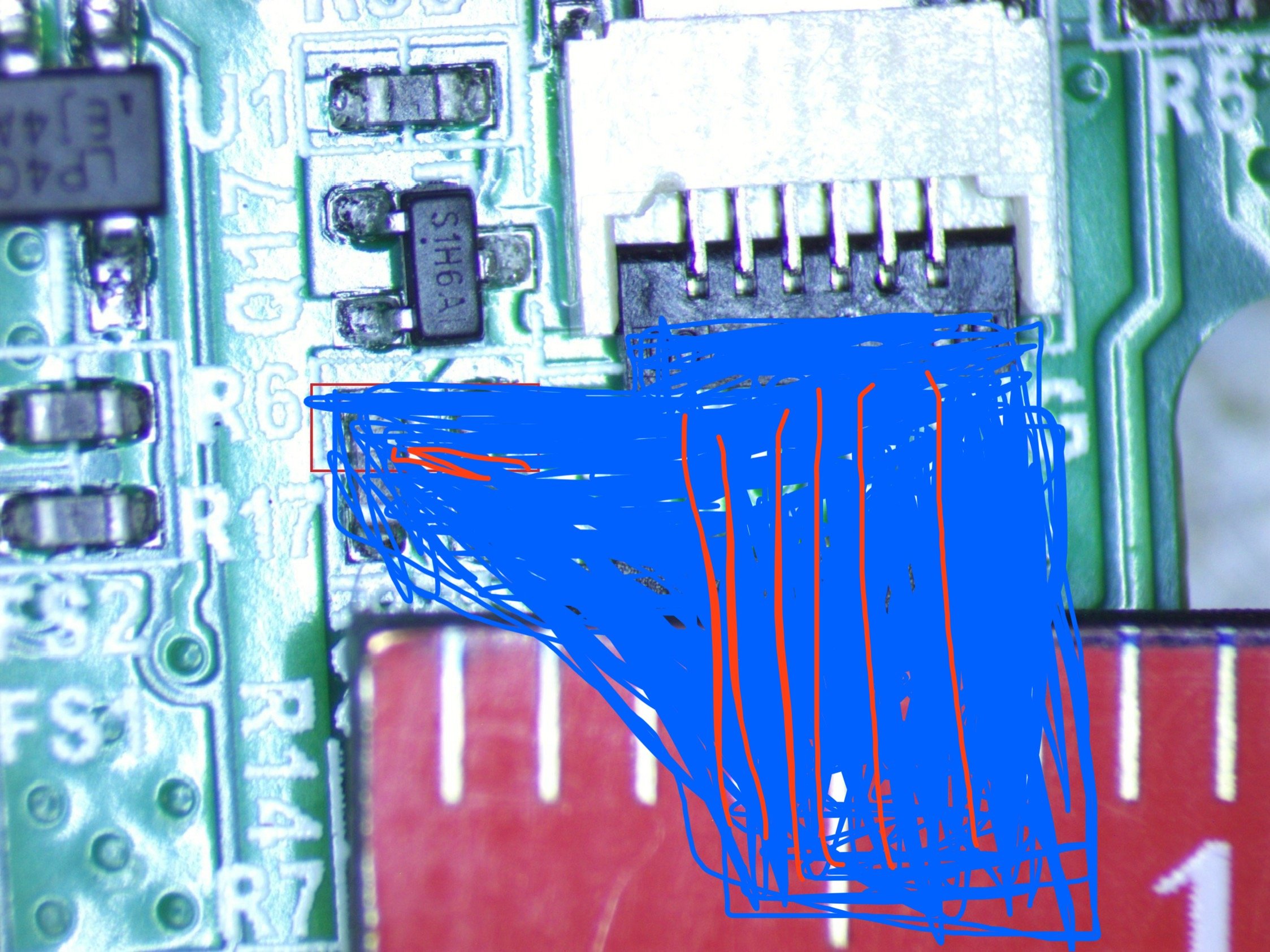
But this is an extremely shoddy solution and i doubt it will last long. You have to hold it firmly in place or the glue will get underneath the component leg. The user can’t let it roll around under the finger. I suggest pressing it against the upper side of the contacts in the picture for leverage. Try it out yourself and see if you can do it. Once you verify with a multimeter you get current through, you can apply more super glue on top between the contacts to give it a little more grip, that may make it hold on for longer. Since it’s for a low current application I’m betting just the contact surface of the component leg with the solder blobs underneath will be enough and will not overheat, but i would suggest letting it run a bit just to make sure. You can always make it just a smidge longer in order for the component leg to wrap around the blobs to increase the contact surface, in sort of a C shape.
A soldering iron for students can be pretty cheap and I’m only suggesting this alternative so you have some sort of low cost solution that doesn’t involve one. Any diode or resistor will do, really, for like 5 cents and superglue for like 2/3€. Or if you want to put it in a kit just send small snips of tin plated, copper clad steel wire, but depending on how many kits you are manufacturing, it might be more cost effective just to use resistor/diode legs harvested from stuff you’ve got lying around.
Any metallic conductive epoxies out there. JB Weld or such
Only need a very tiny well placed drop
Looks like a basic soldering job, give it a touch with resin and fresh solder and create a blob. Even my non-technical grandpa (in his 30s, he needed his 3yo daughter to operate a cassette deck for him!) had a soldering iron for some reason in his shack, and it’s a good skill to have.
I’d need measurements or a better picture but it looks like they might be connected to adjacent pins (3 and 4, where 1 is on the right side from our POV) on the FFC connector. I would try to target that first, there are several options if that is available:
- wrapping both in a loop of thin wire
- wedging a metal item or piece of pencil lead in between (could damage the connector by bending pins if it gets reopened, or the item could dislocate)
- adding a thin strip of conductive foil to the cable’s pins before plugging it in
- on the less-fragile flat cables that use real copper or aluminum strips, the insulation can be reliably removed on the traces in question using gentle force, and then the exposed conductors could be bridged with aluminum foil pressed against the cable by a paperclip, then taped over to prevent accidental shorts. Works with non-adjacent pins too, and can be used on PCBs if you can remove the solder mask on traces near board edges.
Speaking of the last method, you might not need a board edge nearby if you can rely on pressure from the device’s housing:
- Use a knife to gently scrape the solder mask off the traces in question, preferably far from any components.
- Cut a piece of aluminum foil into a shape just big enough to cover both pads.
- Use transparent tape to stick it to the board at the right spot.
- Find or make a foam pad (or similar) of appropriate thickness (which can be determined using modeling clay) to place between the PCB and the housing/bracket/screw. You can use tape to keep it at the spot while reassembling the device.
If applicable, remind them that when screwing screws back into plastic, it is necessary to twist counterclockwise first to locate the original thread and not make a new one, which could ruin it.
pencil, graphite is conductive.
Spit.
Eat some chips first so it’s a little salty.
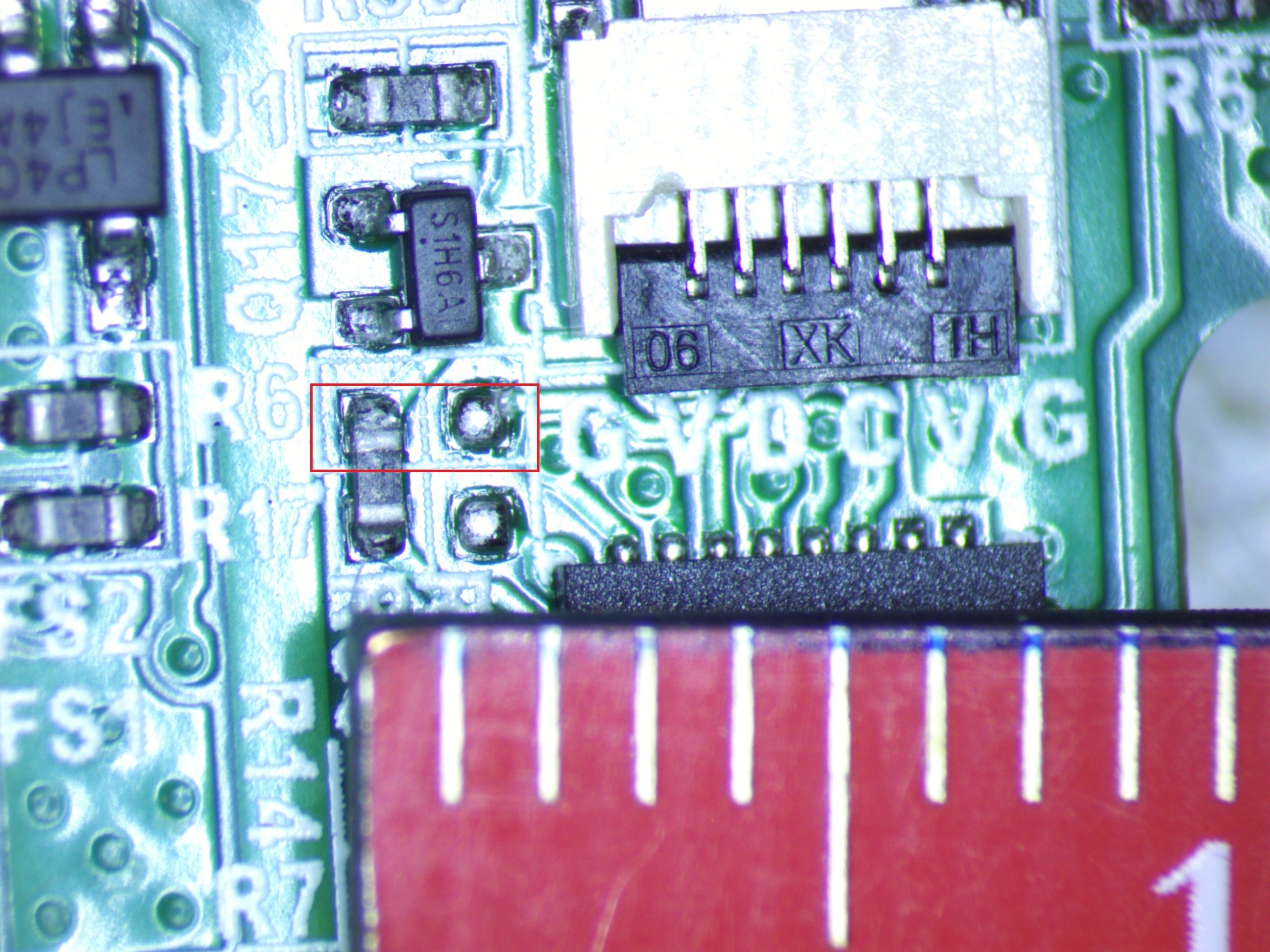
I can’t tell for sure, but it looks like you’re bridging two traces that are connected to the center pin of Q17 (S1H6A) and either the “V” or “D” terminal of the XK ribbon connector with the designators marked “GVDCVG.” perhaps you could use a very small wire between these points. If the V/D connection is actually V and V is for voltage, you can likely find other more convenient places to source a similar voltage around wherever the regulator circuitry for that voltage block is placed on the board.
Yeah, the GVDCVG is ground, voltage, data, and clock. My board is going to sit between this ribbon cable and the part that normally connects there.
You do make a good point though. I was hoping for an elegant solution where this ribbon cable was the only connected component, but there’s a large exposed voltage testpoint exposed nearby. It’s 1.5mm wide and 3mm from the board edge. I bet I can find a miniature allegator clip or some other way to connect to that.
I tell people to take apart an ancient junk switching supply wall wart with a hammer and unwrap a winding from the transformer inside. That gives easy access to a small bit of enameled copper wire. They will need to be extreme about scraping the enamel to get to the copper. It is also a good idea to use a lighter to heat the enamel and scrape some more. Then they can wrap the exposed copper part around something like that transistor lead a dozen or more times like it is an old wire wrap job. If you can locate two such locations where a lead with an air gap exists, it is possible to make that connection.
The circuit in question draws a decent amount of current (probably like 100mA or so), so I thought it better to short the signal line than try to power it directly.
You can get conductive adhesives but it would probably be cheaper to just include a soldering iron in the kit… I’m not sure I would be confident in getting good contact with self adhesive metal tape, your best option there is to probably get a small amount and experiment.
The iron would probably triple the cost of the kit. The ewaste being diverted here is a $17 vape pen.
My point is, for about the cost of an easy solution (that, frankly is a lot harder to undo if done wrong) you could equip them to do it right, practice the skill you want to inspire and not plant the false idea that soldering is some difficult thing that the beginner should avoid.
Design a plastic housing for the connector that puts pressure on short while the ribbon is plugged in. Put a short in the plastic housing.
Making some assumptions here but…
Good idea, but the ribbon connects to the other side of the connector.
That’s still how I’d do it, just make the plastic bit reach over those other resistors. I’d 3d print the bracket.
A thin wire attached to some tape placed perfectly to short them?
Hold a small piece of metal (paper clip?) between solder pads with a tweezer. Heat up tip of a metal fork/spoon (Sharp edge of fork could work better) on a stove. Take it from stove and use it immediately to melt the solder on one pad (seems like there is already enough solder there). I am not sure if it would work but maybe worth trying. Heating entire fork could be hard, so maybe something with smaller metal mass could work better, like a screwdriver, nail clipper etc).
They’ve asked for a good method for a non-technical person, not a bad one for a freaking MacGyver.
Solder is really the only good method. With tape, the adhesive is going to give you really poor contact. With anything else you’re going to struggle to keep whatever you are using to short those pads in place.
Screwdriver
Clip a piece of a copper coin? Tape it down


