

----SOLVED----
Thank you to everybody for your assistance. I managed to get to where I wanted thanks to instructions provided by @dual_sport_dork
Thank you, thank you, thank you!
Not sure if anyone can help me here. I am pretty lost and confused and wouldn’t mind if someone could ELI5 something for me.
I’ve never used a real CAD software before yesterday night and I’m struggling a bit, I tried googling things but it’s just sending me deeper into a rabbit hole of things I do not understand yet.
I’m trying to make this speaker enclosure I’ve seen just to do something with this shitty bluetooth speaker I have, so I decided to recreate the enclosure myself.
Long story short, I realized I kinda screwed myself after disassembling the bluetooth speaker and now I need to make a 2mm deep pocket on top of the case to snap in the buttons module. I don’t really feel like starting the design again from scratch.
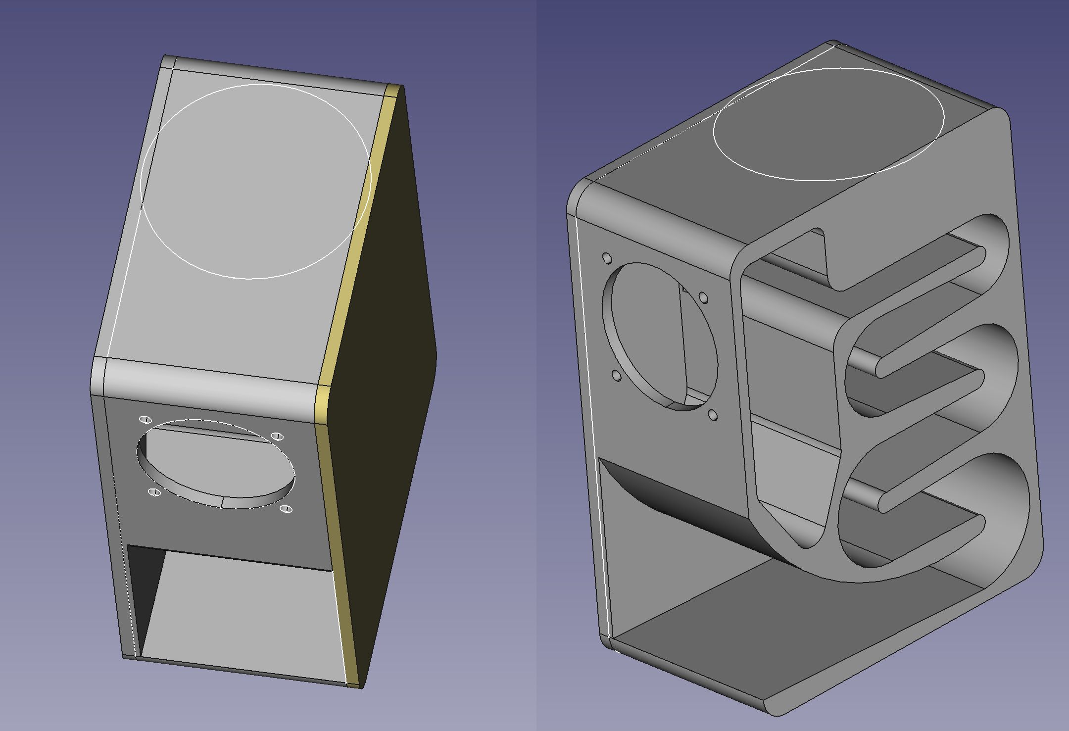
Anyway, as you can see in the attached image, I need to make a big round pocket on top, but both side panels are separate bodies so my pocket only goes through the main body and ignores the 2 other bodies.
I can think of other ways to achieve what I want but I’d really like to figure out a way to do it from where I am right now, if possible. I’ve seen the term shape binder and “union” in my searches but I can’t quite figure it out.
Thank you to anyone who bothered reading this lol
EDIT: For anyone who might see this and is curious about how the enclosure is performing, I finished printing the main body and assembled it to test. Am still missing the side panels and I have to design some kind of flange cover for the driver but here’s what I got so far:
I don’t know about the right way to do this, but here’s what I’d do:
Go into the Draft workbench. Select the sketch for your pocket circle there, and create a Draft Clone of it, which is the blue sheep icon:
This is not the same as the orange sheep “Partdesign_Clone” command found in the Part Design workbench. Don’t ask me why they use the same icon.
If this is the first time you’ve used the Draft workbench, it will “helpfully” slap a grid on your X/Y axis. If you would like that out of your face, click the “Toggle Grid” button, which may be in your overflow toolbar and has thus fallen off of the right edge of the screen:
Anyhow, this will create a linked clone of your sketch. Anything you do to the original will be reflected on the clone(s) if you have to adjust it later. Create two clones, since you need to apply this to two bodies. Drag one each onto the bodies for your side panels (their root icons are that blue stairstep logo). You can then use these to create a pocket or pad or whatever you’re going to do.
If your side panel bodies have their origin set to the same position as your baffle piece in the middle, you won’t have to do anything else. Your cloned sketches will be in exactly the same location as the original. If you moved them relative to the document origin, you may have to scoot your cloned sketches around by fiddling with their coordinates in their Attachment properties.
I have no use for these instructions but wanted to say thank you for taking your time to do this. I have been in this type of situation countless times and would kill for a response like this. Thank you for being helpful and useful to someone in need.
Wow, same here. Upvote just for explaining how to turn that dang grid off!!
Ohhhh I really appreciate you taking the time to write this. I’m gonna have to reread this a couple times for my slow brain to get it but I think I might be able to follow and get it to work.
Thank you so much! I’ll reply back either once I’ve figured it out or right before I blow my brains out!
They’re the same icon because they’re both cloning operations — and I’m sure we’re all familiar with the story of Dolly the sheep, the first cloned animal.
They’re blue and orange because those are the freecad colors for sketch and part respectively.
I get that, but from a design perspective it’s confusing. Making the only difference between two operations that behave differently only color is also not great from an accessibility standpoint, either.
I don’t disagree, was just trying to shed light on the “don’t ask me why” part.
Thank you for your time! You’re so kind!
Okay so I’ve made 2 clones of the sketch from the Draft workbench and put one into each body but it still doesn’t seem to apply the pocket to the other bodies.
Not sure if I did something wrong. Create clones of sketch, place them inside each body container for the 2 side panels, switch back to Part Design workbench, select original sketch and then Pocket. Am I doing this right?
You only cloned the sketch into the other bodies. You still need to use these sketches in each body to create a pocket. So activate one of the side panels for editing (double clicking on the body in the list, so that the name is bold), then selecting the sketch clone and clicking the pocket symbol in the part design workbench. Set its depth and click ok. Repeat for the other side panel
Yuuup just figured that out now. I just had to use the pocket button and not go into the Tasks tab from the Combo View panel. Thank you!
You also have to do a pocket operation to each of the cloned sketches. They will not inherit the pocket from the original sketch – they only inherit the dimensions of the original sketch itself. In the end you will have three total pocket operations, one each on each body.
Each operation applies only to the body it is attached to in the tree.
Omg that was actually so simple. I thought about that too but I never actually used the pocket button I would always just switch to the Tasks tab in Combo View, but for some reason that tab is empty when you select a cloned sketch so I thought that meant whatever I did to the original would just apply to the clones. The button works just fine though.
Thank you so much for your help!